

September 15, 2026. Winnipeg. Manitoba announced it will triple critical-mineral production. The base is not small: provincial mines averaged 78,742 tonnes of critical minerals a year over the past six years. The plan wraps the target in faster environmental approvals for qualified advanced-stage projects, accelerated Manitoba Hydro connections for mines, and fresh money behind the Port of Churchill and its supply corridor.
Permits and power lines help a project start. They do not move slurry. Expansions outrun their thickeners quietly. The tonnage plan goes up, the plant feeds more slurry, and the first warnings stay small — a bed level that creeps, underflow that will not hold its density, process water suddenly spoken for twice. By the time the circuit complains out loud, the thickener has been the bottleneck for weeks. Capacity gets checked in the order the plant feels it: what arrives, what leaves at the bottom, what quality comes off the top.
First calculate the solids and water arriving at the thickener
Dry-solids load sets the mass duty
Start with dry solids. Tonnes per hour, tonnes per day — in the expansion case. Current averages describe the plant that exists. The expansion case describes the plant being designed. Fold in operating hours, the ramp schedule, and the feed range the circuit must swallow on its bad days as well as its good ones.
Ore tonnage at the mine gate is a headline. The thickener never sees it. It sees the solids the upstream circuit actually delivers, at the concentration they actually arrive.
That load decides how much material must settle, compress and leave through the underflow. It also moves while nobody watches. A shift in ore blend or upstream recovery changes solids concentration and settling behaviour with mine tonnage sitting perfectly flat. Design against the stream. Headlines settle nothing.
Hydraulic load sets the liquid duty
Next, the water. Slurry flow plus everything joining it — dilution water, process additions, recycle streams reporting to the same feed.
Concentration does quiet damage here. Fix dry solids at 200 tonnes per hour. At 20 percent solids by weight the thickener receives about 1,000 tonnes of slurry an hour, 800 of it water. At 30 percent solids the same 200 tonnes arrives in roughly 667 tonnes of slurry, 467 of it water. Same mine plan. Same product target. The dilute case hands the vessel a third more liquid to settle and clarify, every single hour it runs.
Two projects with identical dry-solids production hand thickeners wildly different hydraulic duties for exactly this reason. Vessel and overflow system both have to pass the volume the concentration creates.
Separate peaks from averages while you are at it. Averages hide the surge when feed jumps or dilution swings, and thickeners fail at peaks. A circuit that dilutes ahead of the thickener at every start-up builds a hydraulic peak on a schedule. The vessel meets it whether the design allowed for it or not.
Phased expansion? Run the numbers phase by phase. The machine serves the sequence of loads the plant will actually run, in the order it will run them.
Then set the underflow requirement
The discharge must suit the next process step
Only with both loads in hand does an underflow target mean anything. What concentration the next step needs depends on the step: a filtration feed, a leach circuit, tailings transport, a paste system. Each wants a different underflow. Each tolerates a different amount of drift. A filter plant forgives density swings a paste system cannot. A leach circuit counts water arriving with the solids as part of its reagent balance. The requirement flows from the process. Borrow a target from a plant running different ore into a different circuit and you have imported somebody else’s answer.
Track the liquid leaving with the solids, too. Denser underflow sends less water forward — the water balance welcomes that. It also loads the rake and drive harder as the bed deepens. The chosen target must sit inside what the actual slurry allows. Settling and compression behaviour decide that. Uncertain behaviour gets settled by bench or pilot work. A catalogue value answers neither question.
One product example shows how specific a target gets. Our DeepCone Thickener was developed for alumina red-mud separation and washing. Its published figures for that duty: underflow solids 460–530 g/L, final-wash overflow solids at or below 0.2 g/L, underflow alkali at or below 5 kg/t. Those numbers belong to red mud in a washing circuit. Quote them into a Manitoba concentrator design and you have committed a category error. An underflow target is a property of a material and a process. Never of a machine.
Include torque as a changing operating signal
Underflow density and bed depth land on the rake drive as torque. The drive carries the load on the worst day of the bed’s life, not the first.
On our High-Rate Thickener, torque data flows to the control center in real time. The Automatic Clarifier Rake watches rake torque continuously — alarm, or protective shutdown, when resistance turns abnormal. Overload, rake deformation, unplanned stoppages: the failures this monitoring exists to prevent.
A signal earns its keep when the team reads it against the process. Torque rising with a deepening bed says one thing — look at withdrawal. The same rise during a feed surge says another — look upstream. Connect the trend to feed rate, withdrawal and bed behaviour and the number becomes an operating tool. Protection trips are the last line of defence. The mass balance is the first.
Finally confirm overflow quality and water reuse
Clarify how much overflow the plant can return
Overflow becomes “water recovered” only when its destination accepts it. A stream returning to grinding or leaching carries limits — suspended solids usually, dissolved chemistry sometimes. Manitoba’s hydropower-based grid ties water and energy planning close together in these projects, and the expansion may ask for more returned water than the current circuit supplies. A grinding circuit often takes dirtier water than a leach feed can. The limit belongs to the destination, not the thickener.
Define two things together: the flow the reuse points need, and the quality they can take. That pair is the separation duty, in the plant’s own terms. Measure overflow flow and solids as a pair, too. Reuse demand rising while feed chemistry shifts moves the water balance at both ends. Treat overflow as an unqualified by-product and you have sized the thickener for a plant that no longer exists.
Connect monitoring to the control system
The NHD thickener range integrates with the plant DCS — full-process monitoring, automatic control. Ultrasonic sensors read slurry level and solids content in real time. Together with torque and feed flow, the signals describe the whole duty as it runs: what is arriving, what is settling, what leaves at the bottom.
Give each signal a response before start-up. Level trend: check feed against withdrawal. Solids reading drifting: adjust underflow. Torque climbing past its band: the response the team agreed on in advance, not one invented at 3 a.m. Monitoring nobody acts on is decoration.
Check the expansion in the same sequence the plant will run
Reconcile all three duties before choosing diameter
The order is the method. Dry-solids and hydraulic load first — they define what enters. Underflow next — what leaves at the bottom, at what density. Overflow quality last — what the plant gets back. Change any one and the other three get re-checked. A design fitting the solids and missing the water still caps production. It just does it later, at higher cost.
Run the same basis across the current plant, each expansion phase and the final case, normal and peak conditions side by side. Diameter comes out of that work. Chosen first, it is a guess wearing a hard hat.
Match mechanical and control scope to the process
With the duty fixed, the mechanical scope follows: drive arrangement, bearing and lubrication, rake protection, instrumentation, control integration. On the High-Rate machine we run a multi-point drive with a heavy-duty slewing bearing and oil-bath lubrication — the load is sustained and the bearing lives inside it. The tank’s flow field is designed with ADV three-dimensional simulation and Fluent hydrodynamics software. Feed distribution gets engineered before steel gets cut.
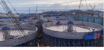
The installed base shows the scale in the same service. For the Lygend nickel-cobalt project in Indonesia we installed three CCD thickeners — Φ32 m, Φ36 m, Φ42 m. The site sits on the Pacific Ring of Fire, so the tanks went in as duplex stainless steel instead of the carbon-steel and rubber-brick design. Structure stayed sound, civil works got shorter, and the client reached its Phase 1 production targets through a pandemic-delayed build. In Papua New Guinea, NHD thickeners include Φ36 m CCD units in nickel-cobalt service, at the Ramu operation that became the first laterite nickel project built fast and brought to full production with designed and actual capacity aligned. The range reaches Φ55 m units in Indonesia and a Φ45 m unit on copper-cobalt in the DRC.
Scope the machine to the duty the calculations produced. Keep utilities in the same conversation. The province can accelerate hydro connections to the fence line. Substations and equipment loads inside the fence remain the project’s own arithmetic.
Conclusion
Manitoba’s faster permits will start more projects than its process plants are ready for, if the sizing work lags the paperwork. The thickener is where that lag shows up first and forgives least: a vessel chosen on averages meets its first real peak in production, in public, with the ramp schedule watching. The projects that hold their ramp will be the ones that ran the arithmetic in plant order while the design could still change cheaply — loads in, underflow out, water back.
That arithmetic is the right place to start a sizing conversation with NHD. Bring the expansion basis — dry-solids load, feed concentration range, the underflow the next step needs, the overflow quality reuse demands — by email to sales@chinanhd.com, and the discussion starts from your plant’s numbers instead of a catalogue diameter. Shorter questions, or a duty that is still taking shape, go to WhatsApp at +86 136 6732 4277.
FAQs
Q1: What should be calculated first when expanding thickener capacity?
A1: The two incoming loads — dry solids per hour and per day, and hydraulic flow with all its additions and recycles. They define the mass and liquid duties. At 200 tonnes per hour of dry solids, the gap between a 20 and a 30 percent solids feed is roughly 333 tonnes per hour of extra liquid, so the concentration assumption alone can resize the vessel. Underflow targets and overflow quality come after, set against those numbers.
Q2: Is 460–530 g/L a universal thickener underflow target?
A2: No. It is the published DeepCone figure for alumina red-mud separation and washing, sitting next to overflow solids at or below 0.2 g/L. A Manitoba sulfide concentrator feeding filters or tailings starts from its own bench work. Different mineral, different process, different target.
Q3: What do torque and ultrasonic measurements tell operators?
A3: Torque shows the mechanical load the settled bed puts on the rake drive. Rising torque warns of overload before the protection trips. The ultrasonic sensors report slurry level and solids content as the circuit runs. Torque climbing with a deepening bed points at withdrawal; torque climbing during a feed surge points upstream. Together the signals show whether the thickener is keeping up with the expansion — or quietly falling behind it.